Product Description
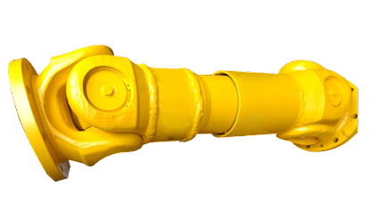
| Product Name | Cardan Shaft |
| Product Model | SWC-I75A-335+40 |
| Main Material | 35CrMo or 45# Steel |
| Nominal Torque | 500 N.M |
| Normal Length | 335 mm |
| Length Compensation | 40 mm |
/* March 10, 2571 17:59:20 */!function(){function s(e,r){var a,o={};try{e&&e.split(“,”).forEach(function(e,t){e&&(a=e.match(/(.*?):(.*)$/))&&1
| Standard Or Nonstandard: | Nonstandard |
|---|---|
| Shaft Hole: | 19-32 |
| Torque: | >80N.M |
| Samples: |
US$ 10/Piece
1 Piece(Min.Order) | Order Sample |
|---|
| Customization: |
Available
| Customized Request |
|---|
.shipping-cost-tm .tm-status-off{background: none;padding:0;color: #1470cc}
| Shipping Cost:
Estimated freight per unit. |
about shipping cost and estimated delivery time. |
|---|
| Payment Method: |
|
|---|---|
|
Initial Payment Full Payment |
| Currency: | US$ |
|---|
| Return&refunds: | You can apply for a refund up to 30 days after receipt of the products. |
|---|

Are there any limitations or disadvantages associated with cardan shaft systems?
While cardan shaft systems offer numerous advantages, they also have some limitations and disadvantages that should be considered. Let’s explore these limitations in detail:
1. Angular Misalignment:
– Cardan shafts are designed to accommodate angular misalignment between the driving and driven components. However, excessive misalignment can lead to increased wear, vibration, and decreased efficiency. If the misalignment exceeds the recommended limits, it can put additional stress on the universal joints and other components, reducing the lifespan of the shaft and potentially causing mechanical failures.
2. Noise and Vibration:
– Cardan shaft systems can introduce noise and vibration into the equipment or vehicle. The universal joints and slip yokes in the shaft assembly can generate vibrations as they rotate, especially at high speeds. These vibrations can contribute to increased noise levels, potentially causing discomfort for passengers or affecting the performance of sensitive equipment. Proper balancing and maintenance of the shaft can help mitigate these effects, but they may still be present to some extent.
3. Maintenance and Lubrication:
– Cardan shaft systems require regular maintenance and lubrication to ensure optimal performance and longevity. The universal joints and slip yokes need to be properly lubricated to minimize friction and wear. If maintenance is neglected, the joints can wear out quickly, leading to increased vibration, noise, and potential failure. Regular inspections and lubrication are necessary to maintain the efficiency and reliability of cardan shaft systems.
4. Limited Flexibility in High-Speed Applications:
– Cardan shafts have limitations when it comes to high-speed applications. At high rotational speeds, the centrifugal forces acting on the rotating components can cause significant stress on the shaft and universal joints. This can result in increased wear, reduced lifespan, and potential failure. In such cases, alternative power transmission systems such as constant-velocity (CV) joints or direct drives may be more suitable.
5. Space and Weight Constraints:
– Cardan shaft systems require sufficient space for installation due to their length and telescopic design. In applications with limited space constraints, it may be challenging to accommodate the full length of the shaft, or modifications may be necessary to ensure proper fit. Additionally, the weight of the shaft can be a consideration, especially in applications where weight reduction is crucial. In such cases, alternative lightweight materials or drive systems may be more appropriate.
6. Cost:
– Cardan shaft systems can be relatively costly compared to other power transmission options. The complexity of their design, the need for customization, and the use of multiple components contribute to higher manufacturing and installation costs. However, it’s important to consider the overall benefits and performance of cardan shaft systems when evaluating their cost-effectiveness for specific applications.
7. Limited Misalignment Compensation:
– While cardan shafts can accommodate angular misalignment, they have limitations when it comes to compensating for other types of misalignment, such as parallel offset or axial displacement. In applications that require significant compensation for these types of misalignment, alternative power transmission systems with more advanced flexibility, such as flexible couplings or CV joints, may be more suitable.
Despite these limitations, cardan shaft systems remain widely used and offer numerous advantages in various applications. By understanding these limitations and considering the specific requirements of the application, engineers can make informed decisions regarding the suitability of cardan shaft systems or explore alternative power transmission options.

Can cardan shafts be customized for specific vehicle or equipment requirements?
Yes, cardan shafts can be customized to meet the specific requirements of different vehicles or equipment. Manufacturers offer a range of customization options to ensure that the cardan shafts are tailored to the unique needs of each application. Let’s explore how cardan shafts can be customized:
1. Length and Size:
– Cardan shafts can be manufactured in various lengths and sizes to accommodate the specific dimensions of the vehicle or equipment. Manufacturers can customize the overall length of the shaft to ensure proper alignment between the driving and driven components. Additionally, the size of the shaft, including the diameter and wall thickness, can be adjusted to meet the torque and load requirements of the application.
2. Torque Capacity:
– The torque capacity of the cardan shaft can be customized based on the power requirements of the vehicle or equipment. Manufacturers can design and manufacture the shaft with appropriate materials, dimensions, and reinforcement to ensure that it can transmit the required torque without failure or excessive deflection. Customizing the torque capacity of the shaft ensures optimal performance and reliability.
3. Connection Methods:
– Cardan shafts can be customized to accommodate different connection methods based on the specific requirements of the vehicle or equipment. Manufacturers offer various types of flanges, splines, and other connection options to ensure compatibility with the existing drivetrain components. Customizing the connection methods allows for seamless integration of the cardan shaft into the system.
4. Material Selection:
– Cardan shafts can be manufactured using different materials to suit the specific application requirements. Manufacturers consider factors such as strength, weight, corrosion resistance, and cost when selecting the material for the shaft. Common materials used for cardan shafts include steel alloys, stainless steel, and aluminum. By customizing the material selection, manufacturers can optimize the performance and durability of the shaft.
5. Balancing and Vibration Control:
– Cardan shafts can be customized with balancing techniques to minimize vibration and ensure smooth operation. Manufacturers employ dynamic balancing processes to reduce vibration caused by uneven distribution of mass. Customized balancing ensures that the shaft operates efficiently and minimizes stress on other components.
6. Protective Coatings and Finishes:
– Cardan shafts can be customized with protective coatings and finishes to enhance their resistance to corrosion, wear, and environmental factors. Manufacturers can apply coatings such as zinc plating, powder coating, or specialized coatings to prolong the lifespan of the shaft and ensure its performance in challenging operating conditions.
7. Collaboration with Manufacturers:
– Manufacturers actively engage in collaboration with customers to understand their specific vehicle or equipment requirements. They provide technical support and expertise to customize the cardan shaft accordingly. By collaborating closely with manufacturers, customers can ensure that the cardan shaft is designed and manufactured to meet their precise needs.
Overall, cardan shafts can be customized for specific vehicle or equipment requirements in terms of length, size, torque capacity, connection methods, material selection, balancing, protective coatings, and finishes. By leveraging customization options and working closely with manufacturers, engineers can obtain cardan shafts that are precisely tailored to the application’s needs, ensuring optimal performance, efficiency, and compatibility.

Can you explain the components and structure of a cardan shaft system?
A cardan shaft system, also known as a propeller shaft or drive shaft, consists of several components that work together to transmit torque and rotational power between non-aligned components. The structure of a cardan shaft system typically includes the following components:
1. Shaft Tubes:
– The shaft tubes are the main structural elements of a cardan shaft system. They are cylindrical tubes made of durable and high-strength materials such as steel or aluminum alloy. The shaft tubes provide the backbone of the system and are responsible for transmitting torque and rotational power. They are designed to withstand high loads and torsional forces without deformation or failure.
2. Universal Joints:
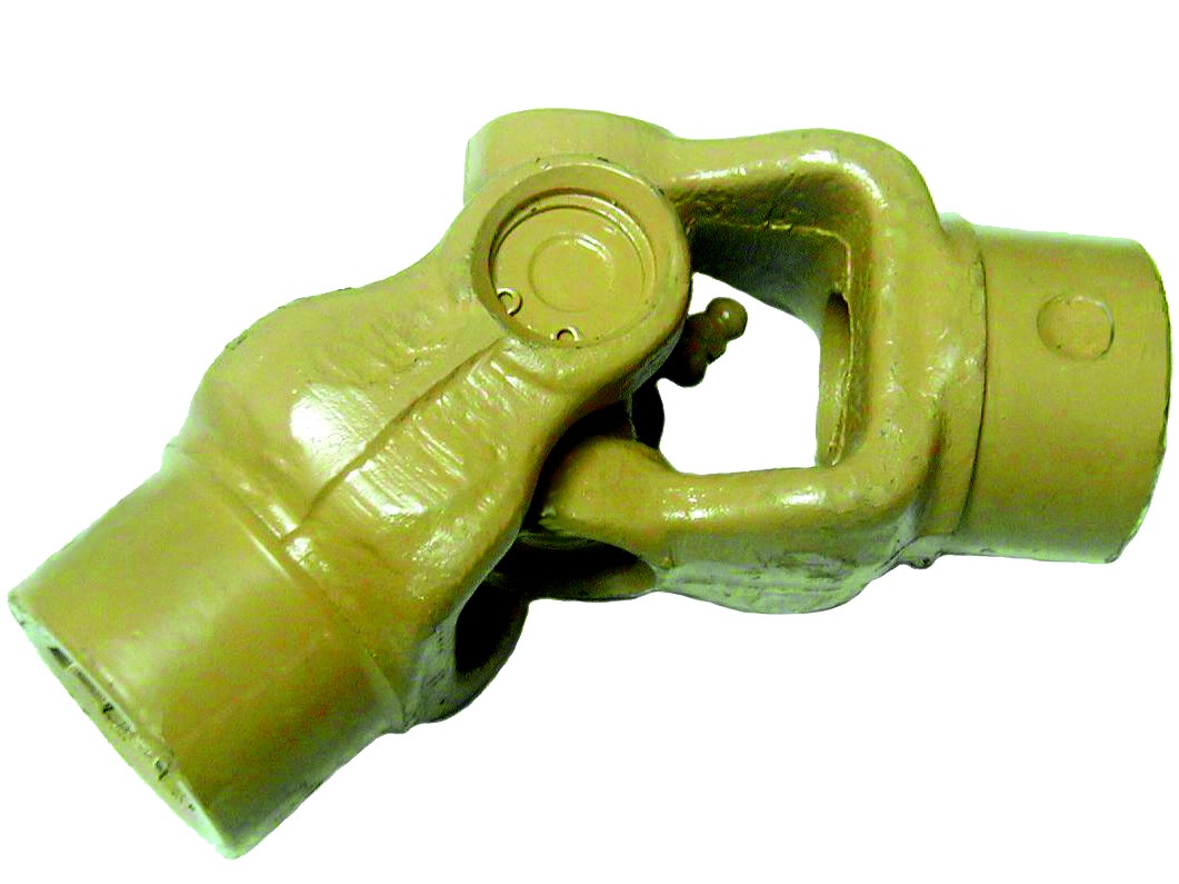
– Universal joints, also known as U-joints or Cardan joints, are crucial components of a cardan shaft system. They are used to connect and articulate the shaft tubes, allowing for angular misalignment between the driving and driven components. Universal joints consist of a cross-shaped yoke with needle bearings at each end. The yoke connects the shaft tubes, while the needle bearings enable the rotational motion and flexibility required for misalignment compensation. Universal joints allow the cardan shaft system to transmit torque even when the driving and driven components are not perfectly aligned.
3. Slip Yokes:
– Slip yokes are components used in cardan shaft systems that can accommodate axial misalignment. They are typically located at one or both ends of the shaft tubes and provide a sliding connection between the shaft and the driving or driven component. Slip yokes allow the shaft to adjust its length and compensate for changes in the distance between the components. This feature is particularly useful in applications where the distance between the driving and driven components can vary, such as vehicles with adjustable wheelbases or machinery with variable attachment points.
4. Flanges and Yokes:
– Flanges and yokes are used to connect the cardan shaft system to the driving and driven components. Flanges are typically bolted or welded to the ends of the shaft tubes and provide a secure connection point. They have a flange face with bolt holes that align with the corresponding flange on the driving or driven component. Yokes, on the other hand, are cross-shaped components that connect the universal joints to the flanges. They have holes or grooves that accommodate the needle bearings of the universal joints, allowing for rotational motion and torque transfer.
5. Balancing Weights:
– Balancing weights are used to balance the cardan shaft system and minimize vibrations. As the shaft rotates, imbalances in the mass distribution can lead to vibrations, noise, and reduced performance. Balancing weights are strategically placed along the shaft tubes to counterbalance these imbalances. They redistribute the mass, ensuring that the rotational components of the cardan shaft system are properly balanced. Proper balancing improves stability, reduces wear on bearings and other components, and enhances the overall performance and lifespan of the shaft system.
6. Safety Features:
– Some cardan shaft systems incorporate safety features to protect against mechanical failures. For example, protective guards or shielding may be installed to prevent contact with rotating components, reducing the risk of accidents or injuries. In applications where excessive forces or torques can occur, cardan shaft systems may include safety mechanisms such as shear pins or torque limiters. These features are designed to protect the shaft and other components from damage by shearing or disengaging in case of overload or excessive torque.
In summary, a cardan shaft system consists of shaft tubes, universal joints, slip yokes, flanges, and yokes, as well as balancing weights and safety features. These components work together to transmit torque and rotational power between non-aligned components, allowing for angular and axial misalignment compensation. The structure and components of a cardan shaft system are carefully designed to ensure efficient power transmission, flexibility, durability, and safety in various applications.


editor by CX 2023-12-19