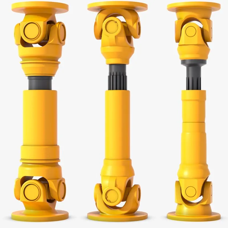
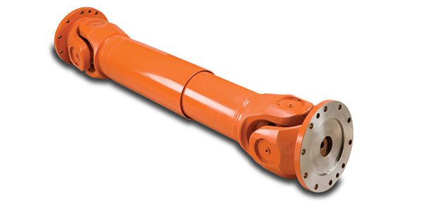
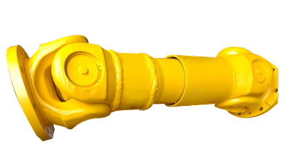
Product Description
Detailed Photos
Product Parameters
|
Brand |
Zhonghe Shengtai |
|
Structure |
FORGING |
|
Material |
Steel, Stainless Steel, Aluminium, Copper, Bronze Or according to customer’s requirement |
|
Processing |
Sawing, Maching, Hobbing, Milling, Shaving, Grinding, Broaching, Heat Treatment, Surface Treatment |
|
Application |
Electrical motors ,Water pump ,gear box spare parts,reducer |
|
Delivery time |
15-30DAYs |
|
Supply capacity |
500 pcs /Month |
|
Certification |
TUV |
Company Profile
CNC Machining Workshop
Our has extensive in-house equipment for both manufacturing and testing. Your parts will be manufactured and inspected with our advanced in-house equipment, Including Precision CNC milling, CNC turning, EDM,We can undertake all kinds of OEM&ODM projects.
Packaging & Shipping
FAQ
Q1:Where can I get product&price information?
A1:Send us e-mail , we will contact you as we receive your mail.
Q2: How soon can I get samples?
A2: Depending on your specific project, it usually takes 10 to 20 days.
Q3:How to enjoy the OEM services?
A3:Usually, base on your design drawings or original samples, we give some technical proposals and a quotation to you, after your agreement, we produce for you.
Q4:Can you make machining parts based on our samples?
A4:Yes, we can make measurement based on your samples to make drawings for machining parts making.
Q5: Is it possible to know how are my products going on without visiting your company?
A5: We will offer a detailed production schedule and send weekly reports with digital pictures and videos which show the machining progress.
/* March 10, 2571 17:59:20 */!function(){function s(e,r){var a,o={};try{e&&e.split(“,”).forEach(function(e,t){e&&(a=e.match(/(.*?):(.*)$/))&&1
| After-sales Service: | Full Service |
|---|---|
| Warranty: | Full Service |
| Condition: | New |
| Certification: | TUV |
| Standard: | GB |
| Customized: | Customized |
| Samples: |
US$ 200/Piece
1 Piece(Min.Order) | |
|---|
| Customization: |
Available
| Customized Request |
|---|

Can cardan shafts be adapted for use in both automotive and industrial settings?
Yes, cardan shafts can be adapted for use in both automotive and industrial settings. They are versatile components that offer efficient power transmission and can be customized to meet the specific requirements of various applications. Let’s explore how cardan shafts can be adapted for both automotive and industrial settings:
1. Automotive Applications:
– Cardan shafts have long been used in automotive applications, especially in vehicles with rear-wheel drive or all-wheel drive systems. They are commonly found in cars, trucks, SUVs, and commercial vehicles. In the automotive sector, cardan shafts are primarily used to transmit torque from the engine or transmission to the differential or axle, allowing power to be distributed to the wheels. They provide a reliable and efficient means of transferring power, even in vehicles that experience varying loads, vibration, and misalignment. Cardan shafts in automotive applications are typically designed to handle specific torque and speed requirements, taking into account factors such as vehicle weight, horsepower, and intended use.
2. Industrial Applications:
– Cardan shafts are also widely used in various industrial settings where torque needs to be transmitted between two rotating components. They are employed in a diverse range of industries, including manufacturing, mining, agriculture, construction, and more. In industrial applications, cardan shafts are utilized in machinery, equipment, and systems that require efficient power transmission over long distances or in situations where angular misalignment is present. Industrial cardan shafts can be customized to accommodate specific torque, speed, and misalignment requirements, considering factors such as the load, rotational speed, operating conditions, and space constraints. They are commonly used in applications such as conveyors, pumps, generators, mixers, crushers, and other industrial machinery.
3. Customization and Adaptability:
– Cardan shafts can be adapted for various automotive and industrial applications through customization. Manufacturers offer a range of cardan shaft options with different lengths, sizes, torque capacities, and speed ratings to suit specific requirements. Universal joints, slip yokes, telescopic sections, and other components can be selected or designed to meet the demands of different settings. Additionally, cardan shafts can be made from different materials, such as steel or aluminum alloy, depending on the application’s needs for strength, durability, or weight reduction. By collaborating with cardan shaft manufacturers and suppliers, automotive and industrial engineers can adapt these components to their specific settings, ensuring optimal performance and reliability.
4. Consideration of Application-Specific Factors:
– When adapting cardan shafts for automotive or industrial settings, it is crucial to consider application-specific factors. These factors may include torque requirements, speed limits, operating conditions (temperature, humidity, etc.), space limitations, and the need for maintenance and serviceability. By carefully evaluating these factors and collaborating with experts, engineers can select or design cardan shafts that meet the unique demands of the automotive or industrial application.
In summary, cardan shafts can be adapted and customized for use in both automotive and industrial settings. Their versatility, efficient power transmission capabilities, and ability to accommodate misalignment make them suitable for a wide range of applications. By considering the specific requirements and collaborating with cardan shaft manufacturers, engineers can ensure that these components provide reliable and efficient power transfer in automotive and industrial systems.

How do cardan shafts handle variations in load, speed, and misalignment during operation?
Cardan shafts are designed to handle variations in load, speed, and misalignment during operation. They incorporate specific features and mechanisms to accommodate these factors and ensure efficient power transmission. Let’s explore how cardan shafts handle these variations:
1. Load Variation:
– Cardan shafts are designed to transmit torque and handle variations in load. The torque capacity of the shaft is determined based on the application’s requirements, and the shaft is manufactured using materials and dimensions that can withstand the specified loads. The design and construction of the shaft, including the selection of universal joints and slip yokes, are optimized to handle the anticipated loads. By choosing appropriate material strengths and dimensions, cardan shafts can effectively transmit varying loads without failure or excessive deflection.
2. Speed Variation:
– Cardan shafts can accommodate variations in rotational speed between the driving and driven components. The universal joints, which connect the shaft’s segments, allow for angular movement, thereby compensating for speed differences. The design of the universal joints and the use of needle bearings or roller bearings enable smooth rotation and efficient power transmission even at varying speeds. However, it’s important to note that excessively high speeds can introduce additional challenges such as increased vibration and wear, which may require additional measures such as balancing and lubrication.
3. Misalignment Compensation:
– Cardan shafts are specifically designed to handle misalignment between the driving and driven components. They can accommodate angular misalignment, parallel offset, and axial displacement to a certain extent. The universal joints in the shaft assembly allow for flexibility and articulation, enabling the shaft to transmit torque even when the components are not perfectly aligned. The design of the universal joints, along with their bearing arrangements and seals, allows for smooth rotation and compensation of misalignment. Manufacturers specify the maximum allowable misalignment angles and displacements for cardan shafts, and exceeding these limits can lead to increased wear, vibration, and reduced efficiency.
4. Telescopic Design:
– Cardan shafts often feature a telescopic design, which allows for axial movement and adjustment to accommodate variations in distance between the driving and driven components. This telescopic design enables the shaft to handle changes in length during operation, such as when the vehicle or equipment undergoes suspension movement or when the drivetrain components experience positional changes. The telescopic mechanism ensures that the shaft remains properly connected and engaged, maintaining power transmission efficiency even when there are fluctuations in distance or position.
5. Regular Maintenance:
– To ensure optimal performance and longevity, cardan shafts require regular maintenance. This includes inspections, lubrication of universal joints and slip yokes, and monitoring for wear or damage. Regular maintenance helps identify and address any issues related to load, speed, or misalignment variations, ensuring that the shaft continues to function effectively under changing operating conditions.
Overall, cardan shafts handle variations in load, speed, and misalignment through their design features such as universal joints, telescopic design, and flexibility. By incorporating these elements, along with proper material selection, lubrication, and maintenance practices, cardan shafts can reliably transmit torque and accommodate the changing operating conditions in vehicles and equipment.

Can you explain the components and structure of a cardan shaft system?
A cardan shaft system, also known as a propeller shaft or drive shaft, consists of several components that work together to transmit torque and rotational power between non-aligned components. The structure of a cardan shaft system typically includes the following components:
1. Shaft Tubes:
– The shaft tubes are the main structural elements of a cardan shaft system. They are cylindrical tubes made of durable and high-strength materials such as steel or aluminum alloy. The shaft tubes provide the backbone of the system and are responsible for transmitting torque and rotational power. They are designed to withstand high loads and torsional forces without deformation or failure.
2. Universal Joints:
– Universal joints, also known as U-joints or Cardan joints, are crucial components of a cardan shaft system. They are used to connect and articulate the shaft tubes, allowing for angular misalignment between the driving and driven components. Universal joints consist of a cross-shaped yoke with needle bearings at each end. The yoke connects the shaft tubes, while the needle bearings enable the rotational motion and flexibility required for misalignment compensation. Universal joints allow the cardan shaft system to transmit torque even when the driving and driven components are not perfectly aligned.
3. Slip Yokes:
– Slip yokes are components used in cardan shaft systems that can accommodate axial misalignment. They are typically located at one or both ends of the shaft tubes and provide a sliding connection between the shaft and the driving or driven component. Slip yokes allow the shaft to adjust its length and compensate for changes in the distance between the components. This feature is particularly useful in applications where the distance between the driving and driven components can vary, such as vehicles with adjustable wheelbases or machinery with variable attachment points.
4. Flanges and Yokes:
– Flanges and yokes are used to connect the cardan shaft system to the driving and driven components. Flanges are typically bolted or welded to the ends of the shaft tubes and provide a secure connection point. They have a flange face with bolt holes that align with the corresponding flange on the driving or driven component. Yokes, on the other hand, are cross-shaped components that connect the universal joints to the flanges. They have holes or grooves that accommodate the needle bearings of the universal joints, allowing for rotational motion and torque transfer.
5. Balancing Weights:
– Balancing weights are used to balance the cardan shaft system and minimize vibrations. As the shaft rotates, imbalances in the mass distribution can lead to vibrations, noise, and reduced performance. Balancing weights are strategically placed along the shaft tubes to counterbalance these imbalances. They redistribute the mass, ensuring that the rotational components of the cardan shaft system are properly balanced. Proper balancing improves stability, reduces wear on bearings and other components, and enhances the overall performance and lifespan of the shaft system.
6. Safety Features:
– Some cardan shaft systems incorporate safety features to protect against mechanical failures. For example, protective guards or shielding may be installed to prevent contact with rotating components, reducing the risk of accidents or injuries. In applications where excessive forces or torques can occur, cardan shaft systems may include safety mechanisms such as shear pins or torque limiters. These features are designed to protect the shaft and other components from damage by shearing or disengaging in case of overload or excessive torque.
In summary, a cardan shaft system consists of shaft tubes, universal joints, slip yokes, flanges, and yokes, as well as balancing weights and safety features. These components work together to transmit torque and rotational power between non-aligned components, allowing for angular and axial misalignment compensation. The structure and components of a cardan shaft system are carefully designed to ensure efficient power transmission, flexibility, durability, and safety in various applications.


editor by CX 2024-02-13